
This site is dedicated to the construction of my road legal electric car. For more info, see my FAQ, above.
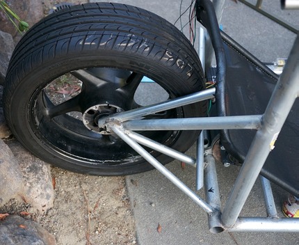
August 31 - Rear wheel attached
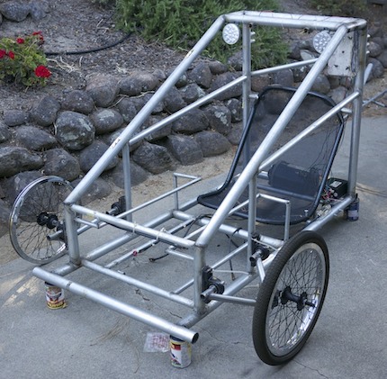
A rather small update today. The rear wheel has been attached, by a rigid single-sided arm. While there was going to be a double sided suspended arm, I switched to single-sided after realizing the complexity of mounting a 6 inch hub with an 8 inch tire. While I could have used spacers and a longer axle, I felt this was a simpler solution. After this change was made though, I realized that suspending the single sided arm was more complex than I had hoped, so to save myself the trouble of this, purchasing a shock, and tensioning the chain, I decided to go rigid. I hope I do not regret this decision.
Secondly, I have done away with the weak looking connections between the front axles and the ball joints. Instead, I simply welded them together, which should be stronger and which resolves my issue of kingpin inclination I had previously. The new connections give close to no scrub.
Next to come are the upper arms, which I will be working on later today. Although I am nearing completion, I am already starting to dream of my next one, which is more than slightly worrying.
August 15 - Rear tire and body work
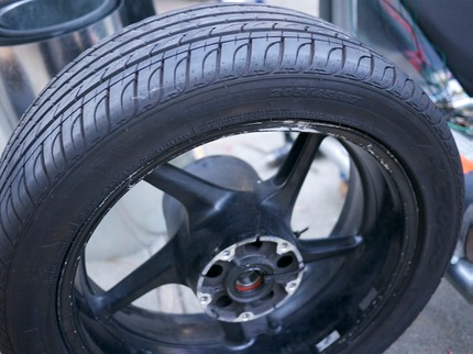
I finally got my rear tire today, from a very nice man who said he had never heard of a project like this in his 25 years of working on cars. It is a 205/45/17, with an outside diameter of about 24.25" and a total weight of 33.4 lbs for the wheel plus tire. This means I can finally begin work on the trailing arm, as well as the rear wheel skirt and the chain drive.
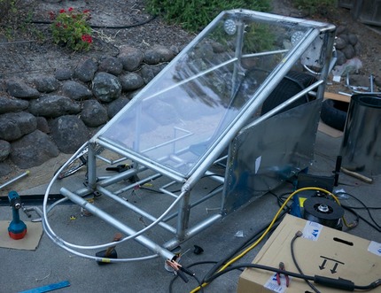
I already began working on other things this week, completing the long overdue tasks of building a "hood" and mounting the windshield, which is also the door. You will notice that I also have my first section of body in. Sadly, that is what will be covering the entire car. It is about 31 gauge galvanized steel, which comes in 20" x 25' rolls for roofing. I know it looks ugly, but I was not willing to pay for and work with fiberglass.
Contrary to what I had read, my Harbor Freight flux welder was able to weld the 31 gauge steel, however it was a difficult and slow task with mediocre looking results, so I decided to simply screw the body on. Here is the welder with the lid cut off and a 10 lb spool mounted in place of the standard 1-2 lb. Amazingly, it still works fine.
August 10 - Suspension
The front suspension is coming together nicely. Aside from some concerns about the strength of the axles, everything seems to be working as planned. I purchased the lower ball joints off a VW Jetta on ebay for 2.50 apiece, and welded a connection to the axle nuts from the BMX wheels I bought. Regarding geometry, camber and caster have yet to be set, however my kingpin inclination was fumbled, and as a result, I have a positive scrub radius, where I would have preferred zero. Camber will likely be set at zero, and caster at 8-10 degrees (positive). Lastly, my track has now been set at 52 inches, which is hopefully not too wide. The complexities of all these variables have gotten me worried about how handling will turn out, but only time will tell.
Next to come are the upper arms, which will be much lighter duty, steering arms, and a steering wheel. In other areas of the car, I have removed the acceleration pedal, as it did not seem strong enough. I have ordered the parts to build a new one, but shipping is estimated to take another week and a half. I hope to have my rear tire soon so I can begin working on the drivetrain and trailing arm, but the technical difficulties therein persist. Turn signals and tail lights are wired and ready to be installed but I have decided to wait until I am working on the body to instal them, as they could easily be damaged.
July 30 – Everything coming together
Once again, a long overdue update. Things are really starting to pick up; I finished my wiring, minus the lights, the batteries have been charged, the motor is running nicely, and the windshield is in. Every day, this project gets closer to completion, and although I will be sad to not have something to work on every day, I am ready to do some test-driving. I still need to purchase some final parts: front wheels and tires, steering bearings, a steering wheel, and the fiberglass for the body, as well as a few smaller things I am surely forgetting, but most everything I need is sitting in my house. A friend is taking care of getting a rear tire for me, which I hope to have back, mounted, suspended, and spinning by the end of next week. In the coming days, I need to weld in some mounting tabs for the suspension bearings, finish cutting and welding my battery cages, hard-wire the chargers to the battery cables, install my side windows, and finish hinging and sealing my door.
In other news, I have made some discoveries regarding my motor. It is a Separately excited DC motor, or Sepex motor, which is said to be the most efficient and tunable of the brushed DC motors (the others being Shunt, Series, Permanent magnet, and Compound), and it has very nice regenerative braking. I also measured the motor speed (using a microphone and sound editing software) to peak at 3200 RPM, which I hope to increase once I am able to edit the programming. Lastly, I have discovered that my controller can give up to 16 horsepower in short bursts, for which the only danger is overheating my motor, so I might have to install a cooling system if I want to run at such high powers.
July 6 - Small Parts
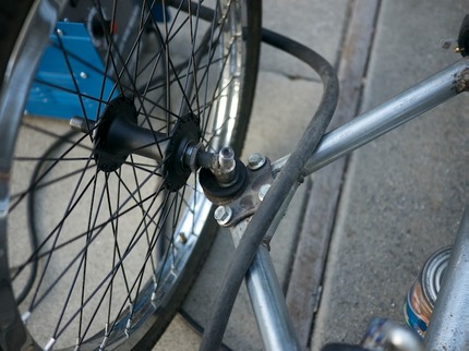
I have returned from vacation with many packages waiting for me, and still more yet to come. Although the chassis is nearly complete, there still remain many less glamorous to be done, including mounting parts, wiring everything, and constructing suspension arms. Since the last update, I ordered about $200 worth of parts online, including front and side windows, lights, wire harnesses, bearings, and programming cables. Most of these have arrived, with some still in transit from Asia. I also purchased my rear wheel, which is quite light, from a Yamaha YZF R1, a very quick motorcycle with over 120 hp.
Also of note is the programming cable. I followed these instructions:
http://www.buggiesgonewild.com/electric-golf-carts/15316-programming-curtis-controller-16.html
These directions were difficult to follow to say the least, however most of the parts seem to be unnecessary. Using a KPG-4 ham radio to USB programming cable, a 74LS04 inverter, a 4-Post wiring harness, another USB cable (for getting 5v to power the inverter), and a computer program, which I have downloaded for free, I think I have created a useable alternative to the $700+ programmer sold by the company.
June 25 - Long overdue update
It has been nearly a month since my last update, and things have really begun to kick off, starting about a week ago. Last Wednesday, I purchased 80 feet of EMT (Electrical Metallic Tubing) from Home Depot, and on Thursday I put down my first weld. I began by welding the two side pieces of the frame to the front bumper, then put in a lateral support under the batteries and one in front of the seat. From there, I built up, testing and checking with my design book, a tape measure, and a protractor to achieve the perfect design. Keeping everything aligned was not too large an issue, as things went pretty smoothly. I also built my seat, out of 3/4" EMT, a tubing bender, some 20lb fishing line, and a yard of Phifertex cloth. At this point, I have the chassis mostly completed, with most of the remaining work on it being mounts for the seat battery box, and suspension. As of tomorrow, there will be no progress until after the 4th of July, as I will not be home. Today, I hope to acquire a motorcycle rear wheel and buy all the parts I need on eBay and McMaster. As with all my entries, I have not gone into details here, but I'd be more than happy to explain anything you may have questions about.
June 4 - Quick Correction
1: MCOR (Top left)
2: MCOR (Top right)
3: MCOR (Bottom middle)
4: Unknown
5: Controller power
6: MCOR (Right)
7: Unused (Reversing alarm?)
8: Input from fwd position of SPDT
9: Controller enabled
10: Input from Keyswitch
11: Unknown (Input from mode switch?)
12: Ground from contactor
13: Speed sensor Ground
14: Input from speed sensor
15: Power to speed sensor
16: Input from reverse position of SPDT
June 2 - Beginnings
Things are beginning to take shape. I have received my motor, controller contactor, and MCOR. As best I understand it, the contactor goes between the batteries and the motor/controller to turn on and off power and is basically a flood-gate actuated by a small current. I believe this current has to do with a microswitch inside the MCOR, which has a 2-prong output. How this is wired remains an enigma. As for the MCOR, this is the accelerator unit, with a potentiometer as well as a microswitch inside. What I think this means is it both turns on the current flow at the contactor and regulates the acceleration by telling the controller how much current to give the motor. It has 5 prongs, one set of 3 and one set of 2. I believe these will go to Pins 4,5,6 and 7,15 on the controller. If you would like to see the controller, along with all the gobbledygook I have spent countless hours wading through, you can download the manual below (Model 1266).
http://curtisinstruments.com/index.cfm?fuseaction=cProducts.dspProductCategory&catID=9
May 18 - Day 1
Hello Readers,
This site was born today, May 18th, after I made payment on my first set of parts. It is dedicated to the construction of a road-legal electric car in my backyard. To build this car, I am starting with a golf cart motor, controller, solenoid, and M-COR, which I have just purchased. As time goes on, I will acquire a set of batteries, chargers, various electronic micro-components, and other various parts, as well as steel tubing, which I will weld into a frame. While all of this may seem unrealistic to you, I should make it clear that it seems the same way to me. However, I am determined, and I am proceeding as I would eat an elephant: one bite at a time.
As far as specifications, my motor is 48v and 3.2 horsepower, or 2.4 kW, for you metric folks. It is off a Club Car brand golf cart, and I believe it is shunt wound, meaning it prefers to run at a constant speed. This already seems like a problem, however the controller I am using, a Curtis 1266, should be able to fix this with some programmable settings.